

With the rapid advancement of high-performance computing (HPC), electric vehicle (EV) battery packs, and high-power-density power electronic devices (e.g., IGBT modules), thermal management technology is undergoing a fundamental shift from forced air cooling to liquid cooling. As the core heat exchange component of liquid cooling systems, the design of liquid cooling plates internal flow channels directly determines the systems heat dissipation efficiency, energy consumption levels, and long-term reliability. This report provides a comprehensive, in-depth, and highly practical flow channel design guide for thermal design engineers, mechanical engineers, and system architects.
This guide not only covers the fundamental theories of fluid mechanics and heat transfer, but also delves into the performance trade-offs of various flow channel topologies (e.g., serpentine, parallel, microchannels, finned channels, etc.). More importantly, the report closely integrates design theory with manufacturing processes (vacuum brazing, friction stir welding, deep-hole drilling, shank teeth, etc.), detailing how process constraints specifically limit design parameters such as minimum wall thickness, depth-to-diameter ratio, and fin density. Additionally, the report addresses material compatibility, working fluid selection, best practices for CFD simulations, and industry-standard testing methods. Through multidimensional in-depth analysis, it aims to assist engineers in designing liquid-cooled plate solutions that meet both thermal performance requirements and manufacturability standards.
2. Background and Core Principles of Liquid Cooling Technology
2.1 The Inevitability and Application Scenarios of Liquid Cooling Technology
In modern electronic devices, the exponential growth in transistor counts on integrated chips has led to a dramatic increase in power density. For instance, various thermal design power (TDP) of high-end server CPUs and AI acceleration cards have surpassed 350W and even 700W, with local heat flux exceeding 100 W/cm². Traditional air cooling, constrained by airs relatively low specific heat capacity (c_p ≈ 1.005 kJ/kg·K) and thermal conductivity (k ≈ 0.026 W/m·K), often faces significant challenges in high-power scenarios due to substantial temperature gradients and noise. In contrast, water or ethylene glycol aqueous solutions exhibit thermal conductivity over 20 times higher than air and specific heat capacity approximately four times greater. These fluids can dissipate more heat with lower flow rates and pumping power, effectively maintaining device junction temperature (T_j) within safe limits (typically<85°c).<>
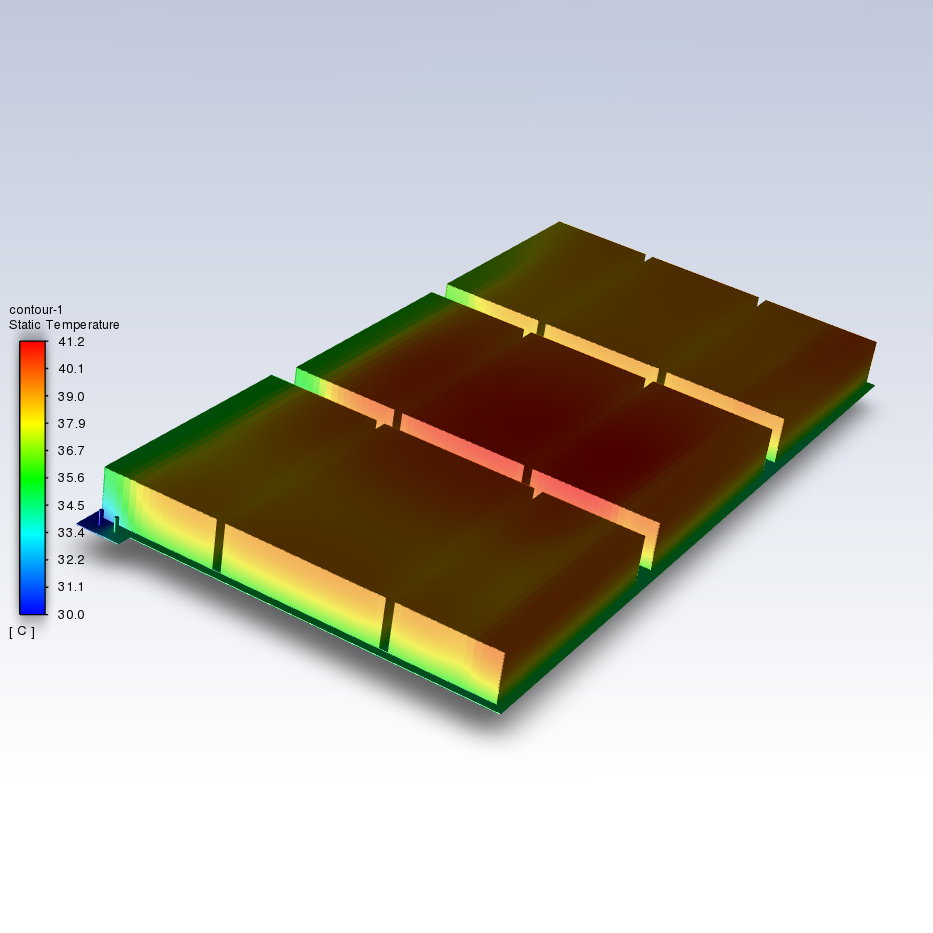
As the core component of indirect contact liquid cooling systems, liquid-cooled plates function to transfer heat from the heat source to a metal substrate through thermal conduction. The cooling medium then circulates through internal channels, dissipating the heat via convective heat transfer. The design aims to minimize fluid pressure drop (ΔP) while maximizing convective heat transfer coefficient (h) and effective heat transfer area (A_eff), thereby reducing overall thermal resistance (R_th).
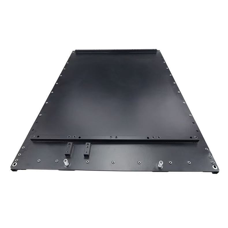
2.2 Physical Composition and Functional Zoning of Liquid-Cooled Plates
From an engineering design perspective, the liquid-cooling plate can be broken down into several key functional zones, each with its own unique design considerations:
1.Thermal Acquisition Zone: This refers to the substrate surface that directly contacts heat-generating components (e.g., IGBTs, CPUs). The zone requires extremely high flatness (typically ISO 12781-2 standard) and minimal surface roughness (ISO 21920-2 standard) to ensure tight bonding with the thermal interface material (TIM), thereby minimizing contact thermal resistance (R_{contact}).
2.Fluid distribution zone (Manifold/Plenum Zone): In parallel flow channels or microchannel designs, fluid must be evenly distributed from the inlet manifold to all branches. The collector chamber design is critical, as improper design can lead to fluid maldistribution, resulting in localized chip overheating.
3.Active Heat Transfer Zone: This is the core of the flow channel design, containing heat-enhancing structures such as fins, pin fins, and grooves. The fluid dynamics characteristics here determine the thickness of the boundary layer and the intensity of turbulence.
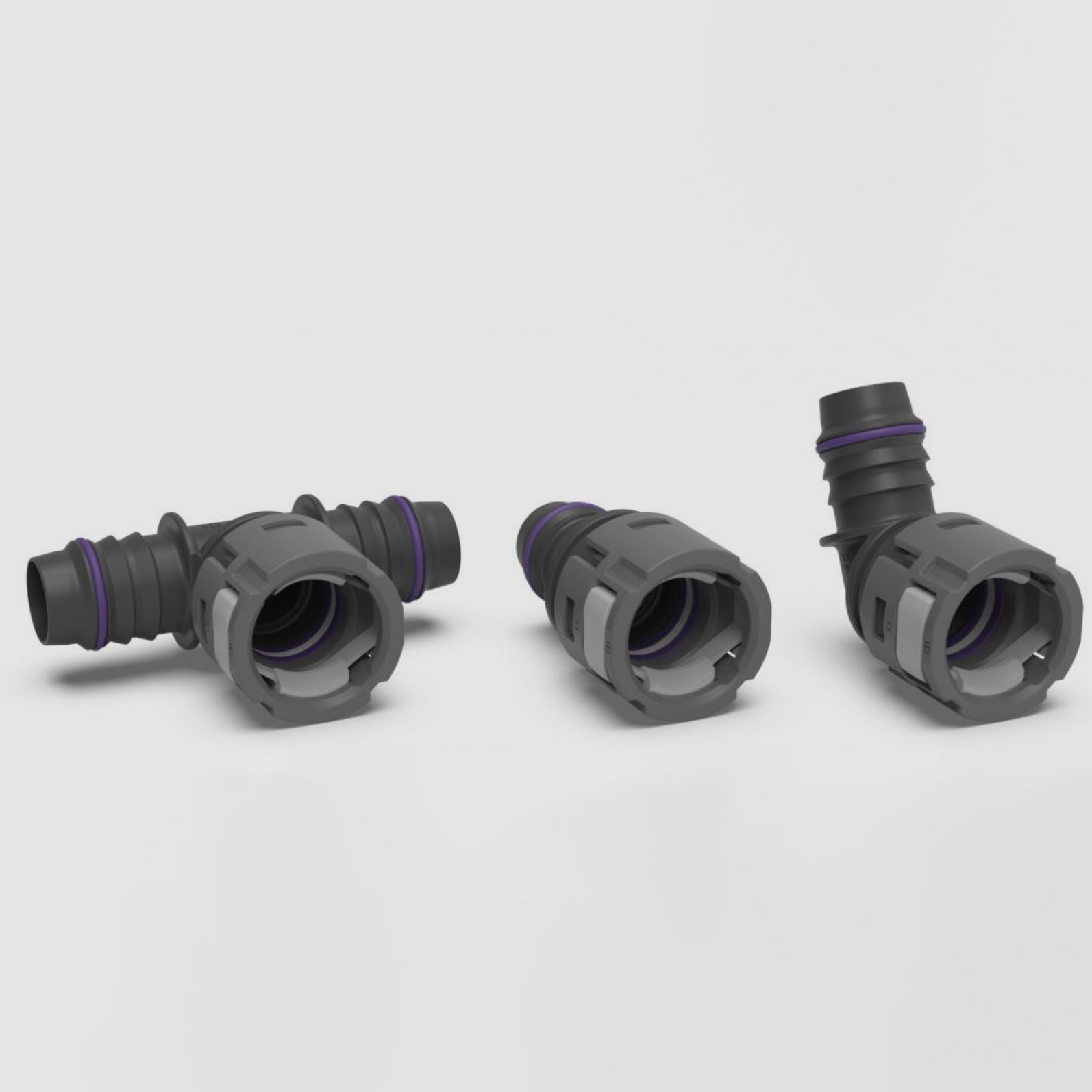
4.Sealing & Connection Zone: This zone involves the bonding process between the cover plate and substrate (e.g., brazing, FSW, bolted gaskets) and the design of inlet/outlet joints. Given the life-threatening risk of liquid cooling system leaks, the design of this zone must comply with stringent reliability standards.
3. Fundamental Theories of Fluid Mechanics and Heat Transfer
The understanding of the physical equations governing fluid flow and heat transfer is the prerequisite for the optimization design. The design of liquid cooling plate is essentially a process of solving the equations of mass conservation, momentum conservation and energy conservation.
3.1 Support Equation and Dimensionless Number
The fluid behavior in the closed flow channel of the liquid-cooled plate is governed by the Navier-Stokes equations. For incompressible steady flow:
Continuity equation (mass conservation): \nabla \cdot \mathbf{u} = 0
Momentum equation (Navier-Stokes): ρ(u·∇) u = -∇ p + μ∇² u
Here, ρ denotes fluid density, u is the velocity vector, p represents pressure, and μ is the dynamic viscosity. The momentum equation demonstrates that the pressure gradient serves as the fundamental driving force enabling fluid to overcome viscous resistance.
Energy equation: ρ c_p (u · ∇T) = k_f ∇²T
This equation describes the balance between heat carried by the fluid (left side of the convection term) and heat diffusion (right side of the conduction term).
To simplify analysis and compare different designs, engineers typically rely on the following dimensionless numbers:
● Reynolds Number (Re): The ratio of inertial force to viscous force, calculated as Re = ρvD_h/μ, where ρ is the fluid density, v is the characteristic velocity, D_h is the hydraulic diameter. This parameter determines whether the flow is laminar or turbulent, making it the most critical factor in flow channel design.
●Prandtl Number (Pr): The ratio of momentum diffusion to thermal diffusion. Pr = c_p μ / k_f. This parameter reflects the fluids intrinsic properties. Water has a Pr of approximately 7, while the ethylene glycol mixture exhibits a higher Pr, indicating a thinner thermal boundary layer than the velocity boundary layer.
● Nusselt Number (Nu): The ratio of convective heat transfer to thermal conduction. Nu = h D_h / k_f. As the key parameter for evaluating heat transfer efficiency, the design objective is to maximize Nu within the allowable pressure drop range.
3.2 Flow State: Trade-off Between Laminar and Turbulent Flow
The core decision of flow channel design is to choose the laminar flow or the turbulent flow, which will change the heat transfer mechanism and pressure drop characteristics fundamentally.
characteristic | Laminar flow | Turbulent Flow |
range of Reynolds number | Re < 2300 | Re> 4000 (transition zone 2300-4000) |
dominant mechanism | Molecular diffusion (thermal conduction), parallel and orderly flow lines | vortex mixing, chaotic motion, intense momentum and heat exchange |
coefficient of heat transfer (h) | The lower value primarily depends on the flow channel dimensions and exhibits a weak correlation with flow velocity. | High, proportional to the 0.8th power of the flow rate (h \propto v^{0.8}) |
Pressure drop (ΔP) | It has a linear relationship with the flow velocity (ΔP ∝ v). | proportional to the square of the flow velocity (ΔP ∝ v^{1.75}²) |
Typical application | Microchannels, high-viscosity fluid | Large-diameter cold plate (gun drilling, tube), water medium |
design strategy | Reducing the hydraulic diameter D_h to enhance the Nu/D_h ratio | Add turbulence-inducing structures (such as fins or pin fins) to induce turbulence. |
Misconceptions and Opportunities of Laminar Flow Design
In microchannel design, although the flow velocity remains low and the flow is laminar, the extremely small hydraulic diameter D_h (typically<1mm) enables="" high="" heat="" transfer="" coefficients="" through="" the="" equation="" h="Nu">
Enhancement methods of turbulence design:
For conventional large-scale flow channels (e.g., deep-hole drilling or buried pipes), relying on natural turbulence may require excessively high flow velocities, resulting in excessive pump power. To address this, turbulence generators (Turbulators) such as twisted bands, corrugated walls, or periodically contracted-expanded structures are often introduced. These devices forcibly induce vortex shedding at lower Reynolds numbers (even Re ≈ 500-1000), thereby disrupting the thermal boundary layer—a technique known as enhanced heat transfer.
3.3 Thermal Resistance Network Model and Heat Transfer Path
The thermal performance of liquid-cooled plates can be analyzed and calculated using a thermal resistance network model. The total thermal resistance R_{total} consists of the following components connected in series:
1.The thermal resistance of the interface (R_{TIM}) depends on the thermal conductivity, thickness, and installation pressure of the TIM material.
2.Thermal resistance (R_{cond}): The resistance to heat transfer through a cold plate substrate. R_{cond} = t/(k_s A), where t is the substrate thickness and k_s is the thermal conductivity of the solid material. Copper (k ≈ 400 W/mK) outperforms aluminum (k ≈ 170-200 W/mK), though this difference may be masked in thin substrate designs.
3.Convective heat transfer resistance (R_{conv}): R_{conv} = 1/(h A_{eff} η_{fin}), where A_{eff} denotes the effective heat transfer area and η_{fin} represents the fin efficiency. This parameter is the most critical factor in flow channel design.
4.Caloric resistance (R_{caloric}): The thermal resistance caused by fluid heat absorption and temperature rise. R_{caloric} = \frac{1}{2 \dot{m} c_p}, where this term reflects the impact of fluid flow rate. Increasing flow rate reduces this resistance, but the benefit shows a diminishing marginal effect.
4. Detailed Explanation and Selection Guide of Flow Channel Topology
The selection of flow channel topology is the core of liquid-cooled plate design. Different topologies exhibit distinct characteristics in heat transfer efficiency, pressure drop, temperature uniformity, and manufacturing feasibility.
4.1 Serpentine Channel
structural description :
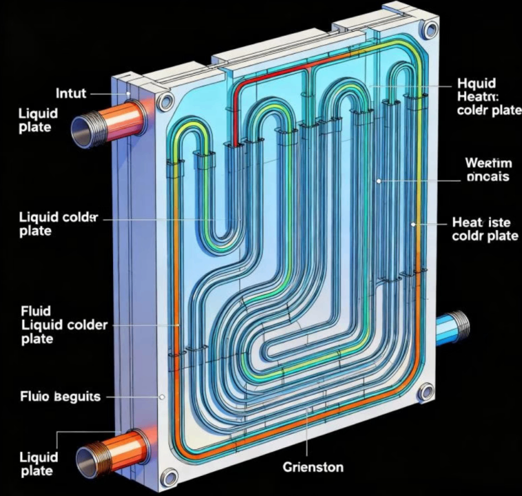
A single continuous flow channel winds back and forth across the substrate plane, covering the primary heat source area. This configuration is commonly found in buried tube cold plates or simple machined flow channels.
Thermal fluid characteristics analysis:
● Flow velocity advantage: With all working fluids flowing through a single path, the maximum flow velocity is achieved at a given mass flow rate. This facilitates maintaining a high Reynolds number (Re) at low flow rates, thereby enhancing heat transfer efficiency.
●Dean Vortices: At bends, centrifugal force generates secondary flow (Dean vortices). This flow significantly enhances radial mixing and heat transfer, but also substantially increases the local pressure drop coefficient K in the bend.
● Thermal gradient effect: As the fluid flows through the channel, its temperature increases progressively, resulting in the wall temperature at the cold plate exit being significantly higher than that at the inlet. This flow-directional temperature gradient (ΔT surface) constitutes a critical flaw for chips requiring uniform temperature (e.g., large GPUs or laser diodes).
applicable scene :
● Low to medium heat flux density applications.
● No strict requirements for uniform temperature, but simplified system control is preferred (single flow path for easier leak detection and flow monitoring).
●Manufacturing process: pipe burial technique, deep-hole drilling (requires plugging to achieve directional change).
4.2 Parallel Flow Channels
structural description :
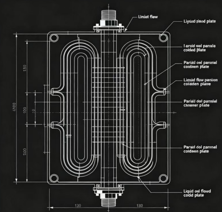
The fluid is distributed through the inlet manifold into multiple parallel branches, then converges at the outlet manifold after passing through the heat exchange zone.
Thermal fluid characteristics analysis:
● Pressure drop advantage: According to the Darcy equation, pressure drop is proportional to the square of flow velocity. When flow rate \\dot{m} is distributed across N branches, each branch experiences a flow velocity drop of 1/N, and the process is shortened, resulting in a significant reduction in theoretical pressure drop (\\Delta P \\propto 1/N^2). This makes parallel flow channels particularly suitable for systems with high flow rates and low pump head.
●Temperature uniformity: The inlet temperature of each branch is consistent, which greatly improves the temperature uniformity perpendicular to the flow direction.
● Flow Maldistribution Risk: This poses the greatest challenge in parallel design. An improperly designed manifold (e.g., with insufficient cross-sectional area) may induce a "Z-shaped" or "U-shaped" flow pattern, creating significant flow disparities between inlet and outlet sections that result in localized hot spots. The standard requirement mandates a manifold cross-sectional area at least 3-5 times the combined cross-sectional area of all branch ducts, or alternatively, a tapered manifold design.
applicable scene :
●High heat flux density, suitable for scenarios requiring high flow rates with limited pressure drop.
● Extensive battery pack cooling (Battery Thermal Management) requires minimal temperature variation between cells.
4.3 Pin Fin Arrays
structural description :
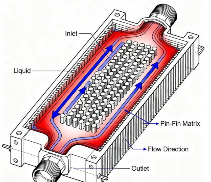
The fluid is arranged in a dense columnar array (circular, square, rhombic or droplet) in the cavity, and the fluid flows around the pin fin.
Thermal fluid characteristics analysis:
● Boundary layer disruption: As a spoiler, the fins not only increase the surface area but also continuously disrupt the development of the fluid boundary layer, generating shedding vortices in the wake region. This intense unsteady flow enables the fin array to achieve extremely high heat transfer coefficients even at low Reynolds numbers.
●Isotropic expansion: Unlike grooves that restrict flow to specific directions, pin fins enable cross-flow of fluid within the plane, making them highly effective for handling hot spots or non-uniform heat sources with uncertain positions.
● High-pressure drop penalty: Winged aircraft primarily generate form drag, with pressure drop typically far exceeding that of straight channels.
●Structural strength: In vacuum brazing or FSW process, the pin fin often serves as structural support columns for the upper and lower cover plates, enhancing the cold plates pressure resistance.
applicable scene :
● Direct liquid cooling for IGBT modules.
●High-end applications requiring extremely low thermal resistance and acceptable pumping head.
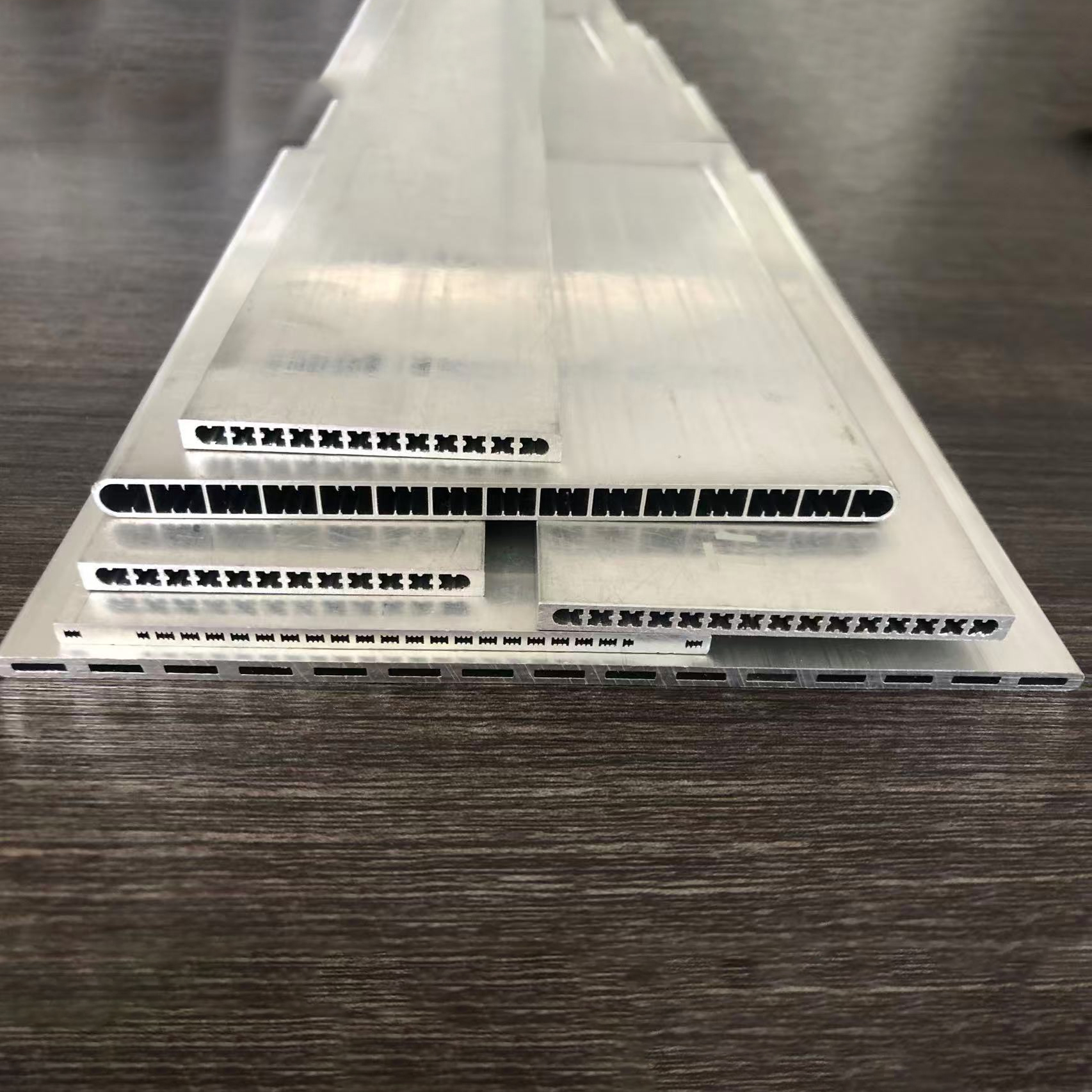
4.4 Microchannels and Manifold Microchannels (Microchannels & MMC)
structural description :
The channel width typically ranges from 50 to 500 micrometers, featuring a high aspect ratio. This represents the current pinnacle technology for high-performance cold plates.
Thermal fluid characteristics analysis:
●Extreme heat transfer: The scale effect enables an exceptionally small hydraulic diameter to achieve a remarkably high heat transfer coefficient (h).
●Length constraint: Traditional long microchannels cause unacceptable pressure drop due to high laminar friction coefficient.
●Manifold-Microchannel (MMC) Innovation: To address pressure drop issues, MMC technology employs a stratified manifold design that vertically channels fluid into microchannel arrays for multi-point discharge. This effectively splits a single long microchannel into multiple ultra-short parallel segments, significantly reducing pressure drop while maintaining high heat transfer efficiency.
applicable scene :
●AI training chips and supercomputer CPUs/GPU.
● Applications requiring extremely high heat flux processing capacity (> 500 W/cm²).
5. In-depth Analysis of Manufacturing Process and Design Constraints (DFM)
Design must accommodate manufacturing constraints. Flow path design without understanding production limitations is merely theoretical. The following table summarizes key design parameters for mainstream manufacturing processes.
5.1 Vacuum Brazing
Vacuum brazing is the preferred process for manufacturing high performance aluminum alloy cold plate, especially for complex fin structure.
●Process Principle: Using a solder with a lower melting point than the substrate (e.g., Al 3003/6061) (typically an Al-Si eutectic alloy such as 4047), the material is melted under vacuum conditions (<10^{-4} torr="">
Design constraints and specifications:
○ Clad Sheet: A standard brazed sheet consists of a core material (3xxx) and a cladding layer (4xxx), with the cladding typically accounting for 5% to 10% of the total thickness.
○ Fin specifications: The standard folded fin (Folded Fin) thickness ranges from 0.05mm to 0.20mm. Fin that are too thin may collapse at high temperatures, while those that are too thick may fail to form high-density corrugations.
○Gap control: The brazing joint surface must be extremely smooth, with the assembly gap controlled within 0.05mm to 0.10mm to ensure effective capillary action.
○ Blind spot cleaning: The design must account for the risk of flux or cleaning solution residue. Although vacuum brazing is typically flux-free, cleaning procedures must still eliminate blind spots.
5.2 Friction Stir Welding (FSW)
FSW is a solid-phase bonding technology that is replacing brazing for cover plate sealing due to its high strength and absence of porosity defects.
●Process Principle: The high-speed rotating mixing head is inserted into the joint, generating heat through friction to plasticize the metal, which is then fused under the action of the mixing needle. The metal remains unmelted throughout the entire process.
●Key design parameters:
○ Cover plate thickness: Recommended range 1.0mm-12mm. Plates thinner than 1mm may tear or collapse under the intense downward pressure from the mixing head.
○ Weld support: FSW requires substantial top forging force, thus the runner design must provide a robust support structure (e.g., substrate stiffeners) directly beneath the weld. Overhanging covers are incompatible with FSW welding.
○Exit Hole: After each welding cycle, the stirring heads withdrawal creates an exit hole. The design must include this hole, typically positioned outside the flow channel seal or subsequently sealed with plug welding or threaded plugs.
○ Flow channel depth-to-width ratio: Since the cover plate requires support, the wide flow channel must incorporate internal support islands, which limits the application of large open flow channels.
5.3 Gun Drilling (Deep Hole Drilling)
The most traditional process involves drilling holes in solid plates to form flow channels.
●Process features: Low cost, no mold fees, ideal for small batches.
● design constraint :
○ Depth-to-diameter ratio: The specialized gun drill achieves a ratio of 100:1 or even 200:1, far exceeding the standard twist drills 5:1 ratio.
○Drift: The drill bit may deviate during long-distance drilling, with a typical tolerance of 1mm/1000mm (or 0.001 inch/inch). Adequate wall thickness allowance must be reserved between holes and between holes and edges during design to prevent drill penetration.
○ Geometric constraints: Only straight flow channels can be machined. Complex serpentine paths require cross-drilling and end-plugging, which increases leakage risks.
○Dead Zone: At the intersection of cross-drilling holes, a flow dead zone forms, where bubbles or sediments tend to accumulate.
5.4 Skiving Process
The metal surface is layered and raised by special tools to form fins, achieving the integration of the substrate and fins (contactless thermal resistance).
● design value :
○ Fin spacing: Minimum 0.1mm, significantly smaller than extruded profiles.
○ Fin height: Aluminum fins can reach up to 140mm, while copper fins are approximately 60mm.
○Height-to-width ratio: The wings can achieve an extremely high aspect ratio, but this increases drag.
○Limitations: The toothed flow channel is typically open and requires a cover plate for sealing (钎焊 or FSW). The toothed surface is relatively rough, which may increase the fluid friction coefficient.
5.5 Die Casting
It is suitable for mass production, especially for automotive battery pack end plates or complex-shaped electronic heat sinks.
● design constraint :
○ Draft Angle: The inner cavity runner wall must have a draft angle of 2° -3° to ensure proper demolding. This means the runner cross-section is trapezoidal rather than a perfect rectangle, requiring correction when calculating the hydraulic diameter.
○Minimum wall thickness: Aluminum die-casting typically requires a minimum of 2.0mm to 3.5mm. Walls too thin may result in poor filling (cold shuts).
○ Porosity: Pressure castings inevitably contain internal pores. Direct use as flow channels may cause minor leakage, thus requiring impregnation treatment.
Comparison Table of Manufacturing Process Parameters
parameter attribute | Vacuum brazing | Friction Stir Welding (FSW) | Gun Drilling | Skiving |
sealing reliability | Medium (Depends on brazing quality, difficult to repair) | extremely high (solid-state forging, pressure resistance>300 bar) | Dependent on plug process | requires coordination with other sealing processes |
flow path complexity | Extremely high (3D flow channels, microchannels) | Medium (limited by weld path and support) | Low (for straight-line combinations only) | High (high-density parallel fins) |
minimum wall thickness | 0.5 – 0.8 mm (internal fins) | > 2.0 mm (force requirement) | > 3.0 mm (anti-drilling deviation) | 0.05 mm (fin) |
fin density | High Offset Fin | low | not have | polar altitude |
mold cost | Gao | Medium (fixture) | not have | Low (tool) |
applicable yield | multitudinous | Medium to large batch | Small batch/prototype | Small and medium batch |
6. Material Selection and Compatibility with Working Fluid
6.1 Selection of Matrix Materials
●Aluminum alloy:
○3003/3004: A molybdenum-based alloy with excellent corrosion resistance and formability, serving as the standard core material for vacuum brazing.
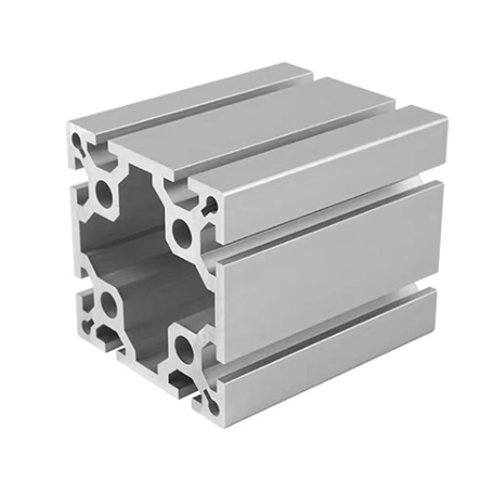
○6061/6063: A magnesium-silicon alloy with high strength and excellent machinability, commonly used for substrates, FSW cladding plates, and extruded profiles.
●Copper:
○C11000 (electrolytic malleable copper): Thermal conductivity ~390 W/mK. Designed for ultra-high heat flux applications.
○ Oxygen-free copper (C10100/C10200): A higher purity grade with hydrogen embrittlement resistance, specifically designed for vacuum electronic device cooling.
○Note: Copper is three times as dense as aluminum, more expensive, and softer (making it more susceptible to erosion by high-speed fluids).
6.2 Cooling Fluid and Corrosion Control
The working fluid is not only a heat carrier but also a part of the chemical environment.
Working fluid type | merit | shortcoming | Material Compatibility Warning |
pure water | Optimal thermophysical properties (high k, high c_p), non-toxic | Freezes at 0°C, conductive, highly corrosive | Conductivity must be strictly controlled, and the mixing of aluminum and copper is prohibited. |
Ethylene glycol aqueous solution | Freezing-resistant (down to-40°C), antibacterial, and preservative | High viscosity (resulting in a surge in pump pressure at low temperatures), with thermal performance inferior to that of water | The concentration is typically 30%-50%. Regular maintenance of inhibitors is required. |
dielectric fluid | Insulation (leakage, no short circuit), inert gas | Extremely low thermal conductivity (1/10 of water), low specific heat capacity, and expensive | The fluorine-containing solution requires specialized sealing materials to prevent swelling. |
Galvanic corrosion:
This is the most common failure mode of liquid cooling systems. When aluminum (anode, potential-0.85V) is electrically connected to copper (cathode, potential-0.20V) in an electrolyte (water), the aluminum will undergo rapid corrosion.
●Design Principle: Mixing aluminum cooling plates and copper radiators in the same circuit is strictly prohibited unless electrically isolated using specialized corrosion inhibitors or Dielectric Unions.
Erosion-Corrosion:
The flow velocity is too high to strip the passivation film on the metal surface.
● design guideline :
The recommended flow velocity of copper pipe is less than 1.5 m/s.
The flow velocity of aluminum flow channel is recommended to be less than 2.5-3.0 m/s.
○ Special attention should be paid to bends and necks, as local flow velocity may increase significantly.
7. Detailed Calculation Method for Thermal and Hydraulic Engineering
Prior to conducting CFD simulations, engineers must perform preliminary screening and parameter configuration through analytical calculations.
7.1 Empirical correlation depth analysis of Nusselt number (Nu)
The accurate calculation of h is the core of thermal design. h = Nu · k_f / D_h.
1. The Nu number (Re<2300) for="" laminar="" flow:="">
In a rectangular flow channel, the Reynolds number (Nu) is determined solely by the aspect ratio (α = b/a, where b is the short side and a the long side) and the thermal boundary conditions.
● Constant heat flux boundary (H2): Suitable for heating electronic chips.
○Square (alpha=1): Nu approx 3.61
○Parallel plates (alpha to 0): Nu approx 8.23
○Shah & London fitting formula 43: Nu_{H2} = 8.235 (1-2.0421 α + 3.0853 α² -2.4765 α³ + 1.0578 α⁴)
○ Insight: Flat flow channels (small α) exhibit higher intrinsic Nu than square flow channels, which explains why flat-tube designs outperform round-tube designs.
2. The Nu number (Re> 3000) for turbulent flow:
●Dittus-Boelter equation: The most classical model, though with a relatively large error (±15%), and is only applicable to smooth tubes. Nu = 0.023 Re^{0.8} Pr^{n} (heating: n=0.4; cooling: n=0.3).
●Gnielinski correlation: This model offers higher accuracy by accounting for the transition zone, serving as the standard model in modern thermal engineering software. The formula is Nu = frac{(f/8)(Re-1000)Pr}{1 + 12.7(f/8)^{1/2}(Pr^{2/3}-1)}, where f denotes the Darcy friction factor. It demonstrates the strong coupling between friction and heat transfer (Reynolds similarity).
3. Correction of serpentine flow channels:
For the curved flow channel, the heat transfer is enhanced due to the presence of Dean vortices. A correction factor can be applied:
Nu_{curved} = Nu_{straight} cdot (1 + C cdot De^m)
The Dean number is defined as De = Re sqrt{D_h / R_c}, where R_c is the radius of curvature.
7.2 Details of Pressure Drop Calculation
Pressure drop calculation must include friction loss and minor loss.
Delta P_{total} = sum left( f \frac{L}{D_h} \frac{\rho v^2}{2} \right) + \sum \left( K \frac{\rho v^2}{2} \right)
● Local resistance coefficient K:
○90° standard elbow: K ≈ 1.0-1.2
○ Round corner elbow (r/D = 1.5): K ≈ 0.2-0.3
○ Overextension/underextension: This depends on the area ratio, typically around 0.5.
○Design Pitfall: In serpentine flow channels with 10180° sharp bends, the local pressure drop may exceed the total pressure drop of straight pipe sections. Fillet optimization must be implemented for the elbows.
7.3 Calculation of Wing Efficiency
For brazing or cold plate with shovelformed teeth, the fin efficiency η fin corrects the temperature attenuation in the fin height direction.
\eta_{fin} = \frac{\tanh(mL_{fin})}{mL_{fin}}, \quad m = \sqrt{\frac{2h}{k_{fin} \delta_{fin}}}
●L_{fin}: Effective height of the fin
●\delta_{fin}: fin thickness
● Design criterion: Target η_{fin}> 0.85. If the efficiency is too low, it indicates that the fin height is excessive or the heat transfer performance is suboptimal. In such cases, increasing the fin height would yield negligible improvement in heat transfer efficiency and instead result in excessive pressure drop.
8. Best Practices for Simulation Modeling (CFD)
Calculation is used for one-dimensional estimation, while CFD is used for three-dimensional optimization. The following is the simulation strategy for the liquid-cooled plate.
8.1 Selection of Turbulence Model
●Laminar flow model: Use only when Re<1500 and="" there="" is="" no="" strong="" disturbance.="">
●k-omega SST (Shear Stress Transport): An industry-standard method. It combines the advantages of k-omega in near-wall boundary layers with the robustness of k-ε in mainstream regions. Particularly effective for capturing reverse pressure gradients, fluid separation, and internal flows in cold plates with complex fin structures.
●k-epsilon: For cold plate simulations involving fine heat transfer surfaces, the standard k-epsilon model tends to overestimate wall heat transfer unless Enhanced Wall Treatment is applied. However, it remains less accurate than the SST model at low Reynolds numbers.
8.2 Grid Division Strategy
● Boundary Layer Mesh: The thermal boundary layer must be solved to accurately calculate h.
○y+ value: Ensure the y+ of the first grid node is less than 1. This allows the solver to directly integrate to the viscous sublayer without relying on wall functions, which is critical for accurate pressure drop and hot spot prediction.
○ Growth rate: The recommended growth rate for the Prism Layer is ≤ 1.2, with a total of 10-15 layers.
● Mesh independence verification: At least three mesh configurations (coarse, medium, fine) must be compared to ensure that the variations in outlet temperature and total pressure drop remain within 3%.
8.3 Conjugate Heat Transfer (CHT)
The simulation must include both fluid and solid domains (cold plate metal, TIM, heat source). Simply imposing heat flux on the fluid surface is not acceptable, as this approach neglects the internal heat diffusion (Spreading) effect within the solid.
9. Testing, Verification and Industry Standards
After the design is completed, it must be verified through rigorous testing.
9.1 Leak Testing
This is the most critical quality control step in mass production.
● Pressure Decay Test: Fill with dry compressed air or nitrogen.
○Pressure: Typically 1.5 times the working pressure.
○ Duration: Maintain pressure for 5-15 minutes, then measure the pressure drop rate.
●Hydrostatic Burst Test: A destructive sampling test.
○FSW cold plates must withstand pressures exceeding 20 bar without rupture.
● Helium leak detection:
● For high-reliability applications (e.g., aviation, medical).
○ With a detection limit exceeding 1 × 10⁻⁶ mbar·L/s, it can detect micro-cracks.
9.2 Thermal Performance Testing
● Thermal resistance measurement: In accordance with JEDEC JESD51-14 and other standards, measure junction temperature (T_{junction}), inlet temperature (T_{inlet}), and input power (Q) under constant temperature water bath and controlled flow conditions to calculate thermal resistance (R_{th}). Plot the R_{th} vs. Flow Rate curve, which typically exhibits an "L" shape, to identify the optimal operating flow rate (Knee Point).
● Flow resistance test (P-Q curve): Measures pressure drop (ΔP) at varying flow rates to verify consistency with simulation results.
9.3 Reliability Testing
● Thermal Shock: Rapid switching of the working fluid between-40°C and +85°C to test the fatigue life of brazing joints or seals.
● Fluid compatibility testing: Long-term immersion to evaluate changes in fluid conductivity and metal ion leaching.
10. Conclusions and Recommendations
Liquid-cooled plate flow channel design is a balance art. It requires engineers to find the optimal solution between thermal performance (high flow velocity, large area, fine structure), fluid power consumption (low flow velocity, short path, large cross section) and manufacturing constraints (minimum wall thickness, process tolerance, cost).
●For extreme heat dissipation (>100W/cm²): We recommend manifold microchannels (MMC) or high-density rake teeth structures. Although these designs entail higher pressure drops and stricter filtration requirements, they deliver unparalleled thermal resistance performance.
●For automotive power batteries: We recommend using Multi-port Extrusion or stamped brazed plates, with parallel flow channels prioritized to ensure uniform temperature distribution while maintaining strict cost control.
●For high-voltage/high-reliability applications: Cold plate with friction stir welding (FSW) process is recommended, offering superior mechanical strength and leak-proof performance compared to traditional brazing, making it ideal for complex power electronics systems.

Contact person:Jason Liu
Tel:+86 15850139786
Phone:+86 15850139786
Email:jasonliu@enjatech.com
Address:No.1998 Jinfeng South Road, Wuzhong District, Suzhou city, Jiangsu Province,China